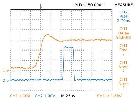
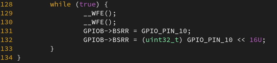
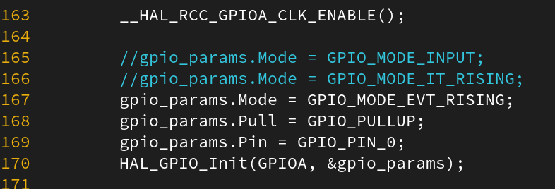
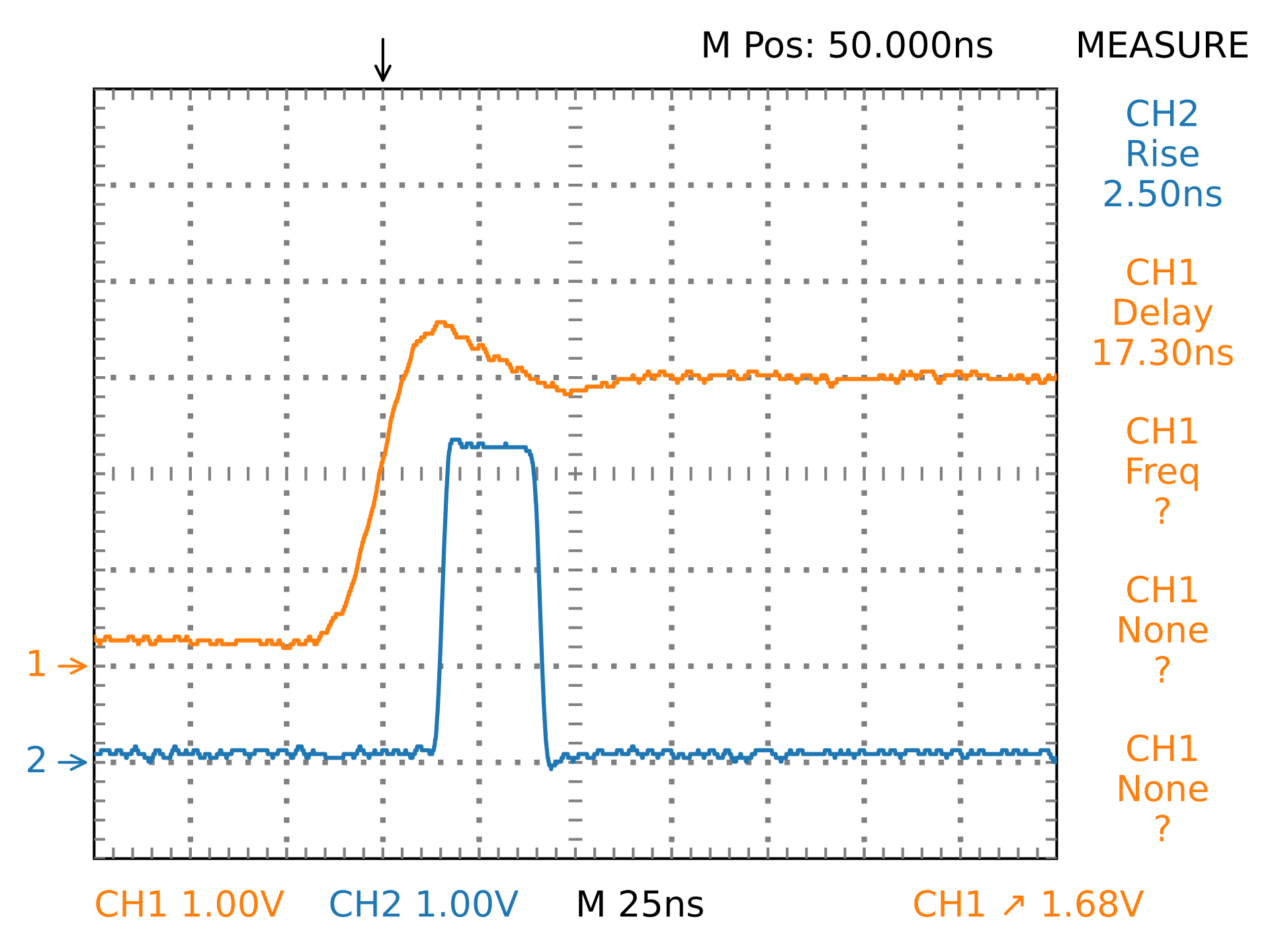
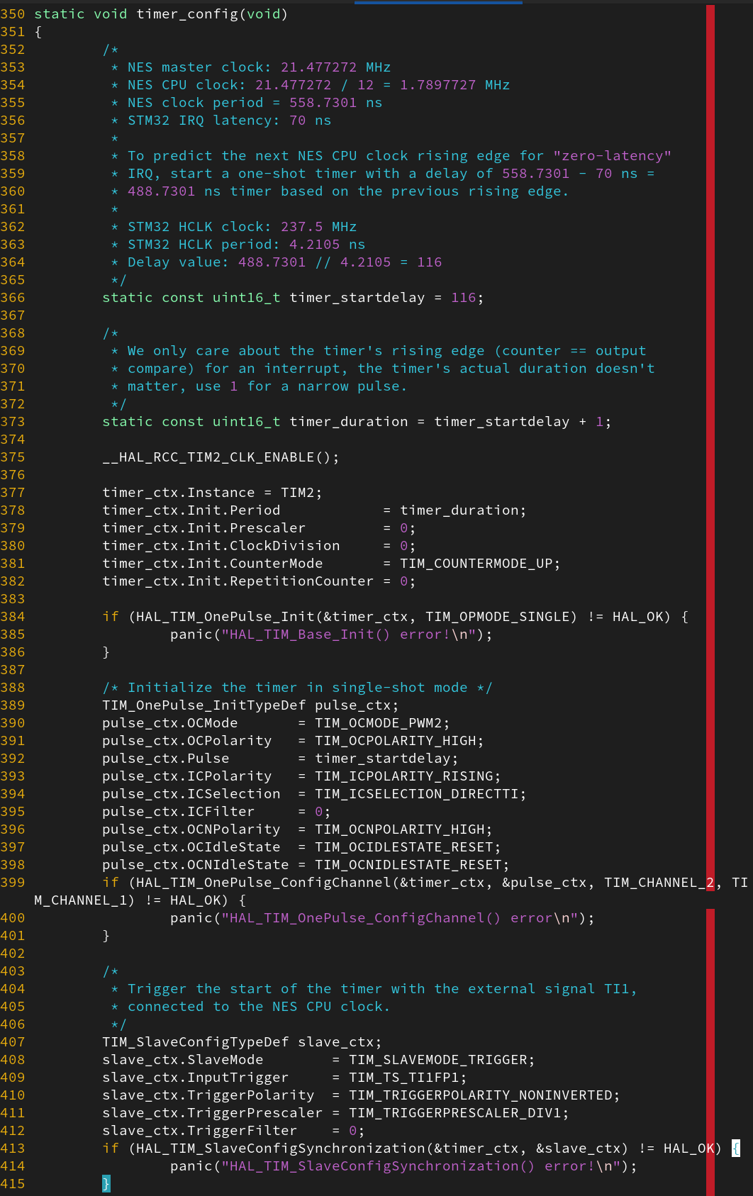
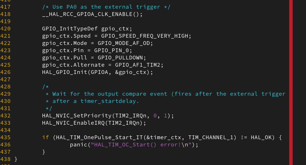
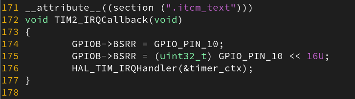
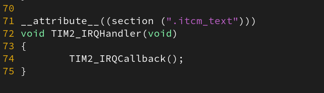
Keep optimizing IRQ latency on the STM32H743 @ 480 MHz. I decided to try an event loop using the WFE instruction instead of IRQs, and I managed to get 60 ns input-to-output latency. I suspect this is the best possible latency. Latency did not improve by abusing QSPI controller to generate a write request (in fact it slightly degraded), even if the QSPI controller is physically close to the CPU. Clearly, passively monitoring signals is not the way to go for bus emulation. Perhaps the solution is predicting the clock before it even arrives, by internally generating a phase-shifted version of it.

Oscilloscope trace, showing a 58.80 ns input-to-output latency on the STM32H7.        while (true) {
                __WFE();
                __WFE();
                GPIOB->BSRR = GPIO_PIN_10;
                GPIOB->BSRR = (uint32_t) GPIO_PIN_10 << 16U;
        }        __HAL_RCC_GPIOA_CLK_ENABLE();

        //gpio_params.Mode = GPIO_MODE_INPUT;
        //gpio_params.Mode = GPIO_MODE_IT_RISING;
        gpio_params.Mode = GPIO_MODE_EVT_RISING;
        gpio_params.Pull = GPIO_PULLUP;
        gpio_params.Pin = GPIO_PIN_0;
        HAL_GPIO_Init(GPIOA, &gpio_params);

Keep optimizing IRQ latency on the STM32H743 @ 480 MHz. My "zero-latency IRQ" idea is a success, now I'm getting a 17.30 ns "effective" latency! Upon receiving every rising edge of the clock, the hardware immediately starts a timer that fires after a programmed delay, calculated to be slightly before the next clock rising edge. This way, the firmware is triggered from recovered, phase-shifted version of the clock, a little bit like how analog NTSC TVs got their H/VSYNC. Interrupt latency is completely eliminated for all but the first clock cycle (which is also predictable with pre-enabled outputs, since it's always the reset vector) Perfect bus emulation starts looking feasible.

Oscilloscope trace of the effective input-to-output latency: 17.30 ns. This latency is not a true latency since it's triggered by the clock's previous rising edge.static void timer_config(void)
{
        /*
         * NES master clock: 21.477272 MHz
         * NES CPU clock: 21.477272 / 12 = 1.7897727 MHz
         * NES clock period = 558.7301 ns
         * STM32 IRQ latency: 70 ns
         *
         * To predict the next NES CPU clock rising edge for "zero-latency"
         * IRQ, start a one-shot timer with a delay of 558.7301 - 70 ns =
         * 488.7301 ns timer based on the previous rising edge.
         *
         * STM32 HCLK clock: 237.5 MHz
         * STM32 HCLK period: 4.2105 ns
         * Delay value: 488.7301 // 4.2105 = 116
         */
        static const uint16_t timer_startdelay = 116;

        /*
         * We only care about the timer's rising edge (counter == output
         * compare) for an interrupt, the timer's actual duration doesn't
         * matter, use 1 for a narrow pulse.
         */
        static const uint16_t timer_duration = timer_startdelay + 1;

        __HAL_RCC_TIM2_CLK_ENABLE();

        timer_ctx.Instance = TIM2;
        timer_ctx.Init.Period            = timer_duration;
        timer_ctx.Init.Prescaler         = 0;
        timer_ctx.Init.ClockDivision     = 0;
        timer_ctx.Init.CounterMode       = TIM_COUNTERMODE_UP;
        timer_ctx.Init.RepetitionCounter = 0;

        if (HAL_TIM_OnePulse_Init(&timer_ctx, TIM_OPMODE_SINGLE) != HAL_OK) {
                panic("HAL_TIM_Base_Init() error!\n");
        }

        /* Initialize the timer in single-shot mode */
        TIM_OnePulse_InitTypeDef pulse_ctx;
        pulse_ctx.OCMode       = TIM_OCMODE_PWM2;
        pulse_ctx.OCPolarity   = TIM_OCPOLARITY_HIGH;
        pulse_ctx.Pulse        = timer_startdelay;
        pulse_ctx.ICPolarity   = TIM_ICPOLARITY_RISING;
        pulse_ctx.ICSelection  = TIM_ICSELECTION_DIRECTTI;
        pulse_ctx.ICFilter     = 0;
        pulse_ctx.OCNPolarity  = TIM_OCNPOLARITY_HIGH;
        pulse_ctx.OCIdleState  = TIM_OCIDLESTATE_RESET;
        pulse_ctx.OCNIdleState = TIM_OCNIDLESTATE_RESET;
        if (HAL_TIM_OnePulse_ConfigChannel(&timer_ctx, &pulse_ctx, TIM_CHANNEL_2, TIM_CHANNEL_1) != HAL_OK) {
                panic("HAL_TIM_OnePulse_ConfigChannel() error\n");
        }

        /*
         * Trigger the start of the timer with the external signal TI1,
         * connected to the NES CPU clock.
         */
        TIM_SlaveConfigTypeDef slave_ctx;
        slave_ctx.SlaveMode        = TIM_SLAVEMODE_TRIGGER;
        slave_ctx.InputTrigger     = TIM_TS_TI1FP1;
        slave_ctx.TriggerPolarity  = TIM_TRIGGERPOLARITY_NONINVERTED;
        slave_ctx.TriggerPrescaler = TIM_TRIGGERPRESCALER_DIV1;
        slave_ctx.TriggerFilter    = 0;
        if (HAL_TIM_SlaveConfigSynchronization(&timer_ctx, &slave_ctx) != HAL_OK) {
                panic("HAL_TIM_SlaveConfigSynchronization() error!\n");
        }
        /* Use PA0 as the external trigger */
        __HAL_RCC_GPIOA_CLK_ENABLE();

        GPIO_InitTypeDef gpio_ctx;
        gpio_ctx.Speed = GPIO_SPEED_FREQ_VERY_HIGH;
        gpio_ctx.Mode = GPIO_MODE_AF_OD;
        gpio_ctx.Pin = GPIO_PIN_0;
        gpio_ctx.Pull = GPIO_PULLDOWN;
        gpio_ctx.Alternate = GPIO_AF1_TIM2;
        HAL_GPIO_Init(GPIOA, &gpio_ctx);

        /*
         * Wait for the output compare event (fires after the external trigger
         * after a timer_startdelay.
         */
        HAL_NVIC_SetPriority(TIM2_IRQn, 0, 1);
        HAL_NVIC_EnableIRQ(TIM2_IRQn);

        if (HAL_TIM_OnePulse_Start_IT(&timer_ctx, TIM_CHANNEL_1) != HAL_OK) {
                panic("HAL_TIM_OC_Start() error!\n");
        }
__attribute__((section (".itcm_text")))
void TIM2_IRQCallback(void)
{
        GPIOB->BSRR = GPIO_PIN_10;
        GPIOB->BSRR = (uint32_t) GPIO_PIN_10 << 16U;
        HAL_TIM_IRQHandler(&timer_ctx);
}__attribute__((section (".itcm_text")))
void TIM2_IRQHandler(void)
{
        TIM2_IRQCallback();
}
0

If you have a fediverse account, you can quote this note from your own instance. Search https://mk.absturztau.be/notes/ajzivgg0k83q01b1 on your instance and quote it. (Note that quoting is not supported in Mastodon.)